The automotive industry is and remains a very important target group for Guhring. We are therefore very interested in how powertrains are changing. We have looked closely at the challenges and the machining of e-mobility components and have developed innovative and reliable tool solutions for our customers.
Today we would like to share this experience with you. My name is Gökmen Sanuk and I am responsible for product management and product development in the cutting materials sector, the PCD PCBN tools. Tailor-made tool solutions are being created in this field based on the component and our customers’ working environments. If you look at the electric vehicle and focus on the cutting volume, three components are particularly present: the electric motor housing, the battery tray as an energy store, and the electric coolant compressor which is installed in heat and cold pumps. The thin-walled electric motor housing covers approximately 100 tools. The stator borehole in particular is dimensioned with very narrow diameters and shapes and position tolerances. Constant temperature control during the machining process is necessary for reliable production of these tolerances. For this reason we recommend using emulsion as the cooling medium for machining electric motor housings.
Electric vehicles generally have a stator borehole with a diameter of more than 200 millimeters. In order to stick to the narrow tolerances of these large diameters on the components, we rely on lightweight construction tools. Our lightweight construction tools have a basic aluminum body and reduce the strain on the machine spindle by up to 60 percent. This means that despite the large bore hole diameter, the narrowest tolerances can be achieved on the component. The stator borehole is machined in three steps. First, the rough measurements are machined in the form of cast pockets with a tangential sheet die. The semi-finished tools pre-machine the stator borehole up to an allowance of 1.0 millimeters in diameter. This creates all the conditions for the finished tool.
Diameter tolerances up to IT6 and form and position tolerances with a tolerance up to one-tenth of a human hair can be achieved on the component. In addition to the narrow tolerances, another challenge in machining the electric motor housing is the defined chip evacuation. The defined chip evacuation is decisive for the component quality. The resulting aluminum chips must not contaminate the cooling fins. The cooling fins surround the state or borehole and can be understood as very narrow cavities. It is very complex and expensive to clean the cooling fins after the machining process.
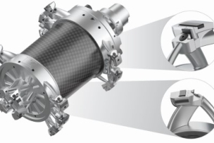
For clean components we rely on additive manufacturing technology. We use additive manufacturing technology when we can achieve technical added value in machining. With a defined chip evacuation we are extending the technical limits of feasibility. For example, three-dimensional cooling duct guides offer considerable added value for chip evacuation. When it comes to milling, we used smart cap. This is an additively manufactured component that is combined with a conventionally manufactured PCD face milling cutter. The innovative geometry of the smart cap enables controlled guidance of the aluminum chip. This greatly reduces the risk of component contamination from aluminum chips during milling.
On the left you can see the conventional PCD face milling cutter and on the right you can see the smart cap solution. See for yourself what difference our tools make. Suring drilling and reaming the tube design tool is used for the defined chip evacuation. This is a PCD tool with an integral chip space. The tube design tool is hollow like a tube. The resulting aluminum chip is evacuated by the internal chip space. This not only keeps the bore hole to be machined clean but also ensures that transverse bore holes and openings on the components are not contaminated with chips. As you can see here, the three-dimensional cooling duct guide with reverse flushing supports chip evacuation. The video shows how the tube design works.
Another important component in an electric vehicle is the battery tray. Depending on the vehicle type there are various dimensions here. On larger vehicles the battery tray can measure up to two meters in length and up to 1 meter in width. The battery tray is machined in two clamping positions with approximately 40 tools. The machining of the battery tray is particularly challenging as the clamping points are far away from the processing surfaces. This leads to an unstable clamping situation. The challenges can be overcome with the help of geometric features such as a high degree of unevenness in the cutting edges and a rigid tool interface with interference optimized tool holders. We are continuously expanding our references and the machining of structural components and especially in battery trays. Today we machine battery trays on all continents and are one of the leading tool suppliers here.
In electric vehicles the components known as the electric coolant compressor in heat and cold pumps is intended for in-vehicle thermal management. This consists of two consecutive spirals, the opposing movement of which compresses a gas. For the most efficient compression the coils are designed with low form and position tolerances. The low wall thickness of less than three millimeters and intrusion heights of up to 30 millimeters require the use of milling tools with minimal cutting pressures. The component requirements are achieved through highly positive helix angles in pre- and finished machining.
We can handle all elements of electromobility from a single source and globally on all continents. We support you worldwide with series production-ready product solutions. Let's tackle these challenges together.


