Sandvik Coromant is the world’s leading supplier of tools, tooling solutions and know-how to the metalworking industry. With extensive investments in research and development they create unique innovations and set new productivity standards together with their customers. These include the world's major automotive, aerospace and energy industries.
One of the manufacturing megatrends of the recent decades is to simplify and minimize the number of machining setups required to produce a specific component. Markets call for shorter lead times and reduced inventories, and this creates a clear incentive for OEMs and perhaps even more so for their suppliers to look for ways to streamline component production as much as possible.
Profitability of a given part may even depend on the capability of combining several setups in a single machine.
One aspect of the single setup trend is adding “live tooling,” or rotating tools, to turning centers. To accomplish this, Y-axis turn-mill machines were introduced in the late 1990s. The first simple types of live tools in turning centers had a significant limitation. Because the rotating cutters were in most machine designs simply added to the turret, they could only be driven in the same two axes of motion as the turning tools, in other words on the X and Z axes. To improve the reach, an extra set of ways was added to move the live tool across the spindle face. This was accomplished by mounting the live tools on revolver sides or on its face, by installing the Y-axis ways on a slanted bed, or by using an independent milling head. Both machine tool makers and manufacturers soon recognized the benefits of this approach. Now, around two decades later, the Y-axis has become a standard feature in nearly all multi-task machines and optional in many new turning centers.
Adding the Y-axis into a turning center provides 90-degrees angularity between the three linear axes, in a way much like a 3-axis machining center.
Challenges in parting-off operations
Parting off is a crucial stage in any turning process where it is required. It takes up only a small percentage of the total cutting time but it is usually the last operation before the part is finished. A breakage of the parting tool can easily result in machine downtime and quality issues, and in a worst-case scenario the workpiece may have to be scrapped and all the value added during previous work stages is lost. Material cost is another major factor. Particularly when working costly materials, such as heat-resistant super-alloys (HRSA), there is a strong incentive to use the narrowest possible inserts.
These factors result in two diametrically opposite requirements for parting tools: They should be as narrow and slender as possible to minimize the loss of material and to optimize the reach of the tool for maximal work diameters. Yet slender tools easily suffer from poor stability and consequently from vibrations and noise. Surface finish and dimensional tolerances ruined by chattering are generally unacceptable risks in parting operations. While the Y-axis substantially broadened the possibilities to use rotating tools in multi-task machines and turning centers, now this capability has inspired a major innovation in one of the original missions of these machine tool types: Y-axis parting.
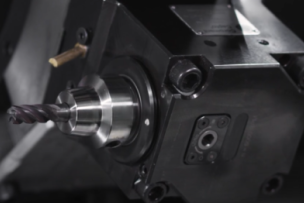
This new parting-off tool and method offer significant productivity and process security improvements in potentially any parting operation. The innovation from Sandvik Coromant, Y-axis parting, is based on an extremely simple principle. While conventional parting-off tools align with the X-axis of the machine tool, the Y-axis tool has simply been rotated 90° counterclockwise to align with the Y-axis. In the conventional parting tool configuration, the relatively long and slender cutting blade and holder is fed at a 90° angle into the rotating workpiece and the largest cutting force is generated by the cutting speed, and the rest by feed motion.
Benefits of Y-axis parting
By turning the tip seat 90 degrees and utilizing the Y-axis, the tool can cut its way into the workpiece essentially with its front end, which nearly aligns the resulting cutting force vector with the longitudinal axis of the blade. The more favorable distribution of forces eliminates critical stresses typical to conventional blades and increases the bending stiffness at a maximum cutting depth (CDX) of 60 mm (2.36 inch) by more than six times. Or, conversely, the susceptibility to plastic deformations and instability is as low as one sixth in the Y-axis design compared with the deformations typical to conventional parting blades. The more than 500% increase in blade stiffness allows substantially higher feed rates and longer overhangs without a loss in stability, which consequently improves the productivity of the tool in equal measure. The general recommendation for parting off bars is to minimize overhang (OH) or, at a long OH, to use a light cutting geometry or to reduce feed. A common threshold value for reduced feed is an OH exceeding 1.5 times blade height. With Y-axis tooling, longer overhangs can be achieved without settling for less than optimal feed rates, cutting geometries or tool dimensions.
Thanks to the increased stiffness and consequently reduced bending, Y-axis tooling may eliminate the need for over-center settings and prevent the related disadvantages such as premature insert breakages when pushing through center and rapid flank wear. Other benefits include lower noise levels, better surface finish and a more reliable process as well as the capability to part off larger diameters than currently possible.
Machine-specific aspects of Y-axis parting
Turning centers: Generally used for mass production from bar stock, typically 65 mm (2.56 inch) in diameter. In this type of machining, the biggest benefits of Y-axis parting are improved productivity and surface quality. The opportunities for quality optimization can also be interesting, since parting off is typically the last stage for a component. An additional opportunity is to improve the machining economics by reducing the parting width.
Multi-task machines: Y-axis parting blades primarily offer increased accessibility and capability for larger diameters. A pre-test confirmed a 50% increase in the overhang when cutting a conventional 120-mm diameter bar at the maximum feed capacity of the insert. A 300% productivity increase was achieved with no process security complications. In a customer test case, Y-axis parting successfully replaced band sawing for a 180-mm diameter Inconel bar, resulting in significant productivity improvement thanks to dramatically shorter machining times.
Slant-bed machines: Typically, the X-axis creates an "uphill" slanted towards the front of the machine, with spindles on one or both side ends of the slant bed, and the X-axis travel is usually substantially longer than the Y-axis travel. The resulting work space limitations must be considered when considering the usability of Y-axis parting for a specific component. In a multi-task machine, which essentially could be characterized as a machining center with turning option, typical tool assemblies, such as Coromant Capto® C6 or HSK63T blade adaptor, are often relatively long to enable sufficient reach between the main chuck and sub-chuck. Because of this, the total setup is weak in the X direction compared to the Y-axis load, where the cutting force is directed into the tool assembly and into the machine spindle. Typical Y-axis tool assemblies, usually based on a VDI adaptor or a bolt-on blade adaptor for the machine-adapted clamping unit (MACU), are long and slender to reach between main- and sub-chuck and allow parting off close to chuck.
Getting started
An investment in Y-axis parting is first and foremost a change in the approach to parting operations and the related ways of working. It offers a way to more fully utilize the capabilities of machines already fitted with a Y-axis. Alternatively, it is an option that can substantially increase the productivity of parting operations in a new machine or a modified process setup. Y-axis parting can even offer a chance to reduce the tool inventory because there is less need for dedicated blades since the new Y-axis blades fit in standard adaptors and use standard CoroCut® QD inserts.
As a practical consideration, it should be noted that the cutting edge is 7 mm (0.276 inch) above the Y = 0 position when mounted on a standard blade adaptor. The operator should make sure that this protrusion is offset in the CNC program.
Watch Behind the Scenes of Y-Axis and Demo Y-Axis.


Talk to Us!
Wouldn't the same/similar stiffness be obtained simply by using a taller blade in conventional parting?
IOW, going from a 1/2" tall cutoff blade to a 2" tall blade?
30I am curious about y axis parting off. The machine I am mostly interested in runs diameters of 1-1/4 up to 3 inches. The material varies, but mostly will be 1018, 1045, 1144, 4140HT, along with 303, 304, and 17-4 SS. Can you give me an idea of the speeds and feed I could expect with your system, and make a recommendation for a blade and inserts that would work best for us?
21Leave a reply
Your email address will not be published. Required fields are marked *