Share

The list of aircraft parts now being made with composites has grown longer than a TSA screening line. Then add in the newer metal-matrix composites (MMCs) and ceramic-matrix composites (CMCs), things like the fan in the hot zone of the engine. Composite use is growing, and methods for machining them is advancing.

The list of aircraft parts now being made with composites has grown longer than a TSA screening line: the fuselage, empennage (tail section), wings (including skins, stringers, spars, clips, and wing boxes), nacelles, control surfaces (ailerons, flaps), nose skin, and even floor beams. Plus internal non-airframe components like levers, interior braces and panels. Oh, and helicopter rotors.

Then add in the newer metal-matrix composites (MMCs) and ceramic-matrix composites (CMCs), things like the fan in the hot zone of the engine. Composite use is growing, and methods for machining them is advancing.

CFRP Still Top Dog

Carbon fiber reinforced plastics (CFRPs) still represent the most commonly used composites in aerospace, in both weight and part value. There are variations in resin matrices used, fibers, and fiber layup and curing methods, all of which can affect machining. But the basic challenges are how to cut them with sufficient accuracy and speed without causing delamination, fiber tearing, fiber pull-out, or heat damage. Naturally, traditional machining technology is a common choice. But CFRP doesn’t cut into nice, heat-removing chips as much as splinter into dust, and a very abrasive dust at that. That has led to the development of polycrystalline diamond (PCD) and diamond-coated cutting tools of increasing sophistication.

As Joel Macklin of Royal Engineered Composites Inc. (Minden, NE), a manufacturer of aerospace composites, explained, “Diamond is an excellent heat conductor, so a diamond tool helps conduct the heat out of the cutting zone. Heat is the enemy of the coating and will cause it to fail prematurely. And of course you also don’t want heat in the CFRP because it damages the matrix. So you need to remove the heat from both the tool and the part.”

Compression routers are ideal for CFRPs because their opposing helixes help prevent delamination. Sandvik’s 2P460 has overlapping long right-hand and left-hand cutting edges, making it suitable for both thin and thick laminates.

For Aaron Howcroft, Global Product Manager—Composites & PCD for Sandvik Coromant (Fair Lawn, NJ), “the primary benefit of diamond tooling is its ability to withstand abrasion, not so much its ability to transfer the heat.” He agreed that the dust produced by machined composites removes only a little heat and that diamond transfers heat well. But he says it’s a secondary factor in actual machining. His recommendation is to feed faster than might seem wise.

“Some customers try a very high RPM and maintain the same feed rate,” explained Howcroft, “but that makes the heat situation worse. They are generating more heat and not trying to get away from it any faster. We typically recommend moderate RPMs with higher feed rates. You can go a lot faster per tooth with carbon fiber than most other materials and as a result it helps move ahead of any heat buildup.”

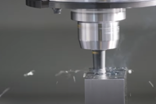
Don Graham, a recently retired scientist from Seco Tools LLC (Troy, MI), echoed this and added, “We worry about the radial depth of cut [DOC] when machining composites with traditional milling cutters. The greater the radial DOC, the greater the temperature will be. So controlling the arc of contact between the round tool and the composite is critical. We prefer to minimize this as much as we can and increase RPMs and feed rates to compensate.”

Coolant or Not?

Of course applying coolant is the other obvious way to remove heat from the cut and in most cases there appears to be no risk to the composite that would prohibit this (honeycomb composites being a notable exception). As Howcroft put it, “In my experience, it usually depends on what the facility management allows. It’s rarely up to the process engineers and I talk to many who want to use coolant but can’t. The only recommendation of ours they are likely to follow is if we ask them to turn coolant off for a given application.”

Barrington McCullough, technical sales machining, Fives Cincinnati (Hebron, KY), said most of his company’s customers prefer to machine dry, or occasionally with a minimal mist. “Cutter life is definitely a concern, but in the tests we’ve done, cutting wet didn’t seem to gain much value.”

From his perspective, Adrien Roubenne of Fives Liné Machines (Granby, QC) said, “Dry machining is generally used by Tier 1 and 2 manufacturers for medium-sized parts and definitely for honeycomb. But OEMs machine their largest parts, like the central wing box or wing skins, 100% with coolant to improve tool life and reduce the risk of overheating. But [this] is expensive because you have to use a lot of coolant and remove swarf with an expensive coolant filtration system.”

Solid Versus Coated Diamond

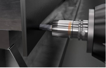
Everyone interviewed for this article agreed that composite tooling is generally small in diameter: drills between 4 and 10 mm in diameter and routers between 10 and 12 mm, and therefore solid round tools versus indexable tools. Minimizing vibration is critical, so tool balancing combined with shrink-fit holders are the most common solution. And tools should be as short as possible for the same reason. Everyone also agreed that you want an extremely sharp edge to cut CFRP, which leads us to the debate about whether a “solid PCD” tool (i.e. incorporating PCD wafers) is better than a less expensive diamond coated tool (generally coated via chemical vapor deposition, or CVD).

According to Graham, “Solid PCD allows you to create a cutting edge with a radius under 10 µm, depending on how you measure it and what you call the ‘edge.’ With a diamond coating, the best you can do is roughly 20 µm. As a result, you run the risk of delamination and tearing fibers. So diamond-coated tools are typically restricted to smaller batch production, prototypes, and other applications where the cost of the tool becomes more important.”

On the other hand, Graham and others said diamond coatings are becoming very good and some manufacturers improve edge sharpness with post processing. So if there’s any concern about an inexperienced operator chipping a tool, you’re better off avoiding solid PCD. As Macklin put it, “Solid PCD tools work really well in certain applications. But it’s also much more sensitive in that if you get any pit, nick, or damage to the edge of the PCD it quickly becomes unusable.”

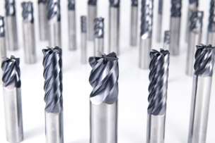
If you have a skilled staff, high part volumes, and need to maximize throughput, solid PCD tools may be worth the extra cost. Also, many more options exist than a few years ago. In addition to straight helix tools with brazed carbide inserts, companies like Sandvik Coromant and CITCO Tools, a division of Fives Landis Corp. (Concord Township, OH), now offer veined PCD tools, in which PCD wafers go through the heart of a carbide blank, like a vein of coal in sedimentary rock. This enables the use of helical flutes. And thanks to advances in laser ablation and electrical discharge grinding technology, Sandvik Coromant’s Howcroft said, “We can do variable helix, unequal indexing, chipbreakers, special configurations on notches, surface texturing…”

In other words, you can now get the latest in milling geometries in solid PCD, which just might be the solution to your toughest problems. And although solid PCD tools still cost significantly more than CVD diamond-coated tools, Charlie Novak, product manager for CITCO Tools, said prices for all forms of PCD tooling have come down. Plus, solid PCD tools can be reconditioned, a process that’s difficult to do effectively with CVD tools.

Whether solid PCD or diamond coated, compression routers have long been favored for trimming CFRP because they compress the laminate while cutting it, helping prevent delamination. It’s the combination of right- and left-hand helixes that create that compressive force, but these routers have generally been limited to thicker laminates due to a gap between these cutting edges where they would otherwise meet. Sandvik Coromant’s new 2P460 compression router features overlapping right- and left-hand flutes, making it suitable for both thicker and thinner materials. “In other words, said Howcroft, “you get a compressive cut on any thickness. And the tool works especially well on thinner material because it also eliminates harmonics by reducing vibration.”

What about Waterjet?

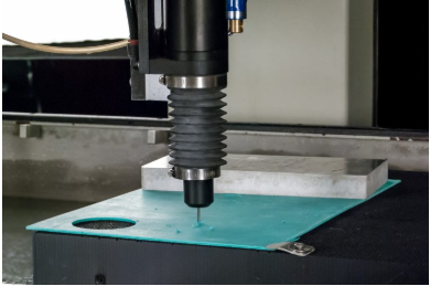
For many applications, especially trimming, the best solution may well be to forget rotating cutting tools and instead cut with abrasive waterjet.

As Stephen Bruner, Vice President of Marketing for Omax Corp. (Kent, WA) explained, “The benefit that waterjet offers is it’s a cold cutting process. Waterjet imparts no chemical changes to the part and creates no heat-affected zone that in any way alters the material properties. This applies to material types that range from glass-filled or carbon-filled composites to metals.”

Simon Kenworthy, Business Development Manager for Shape Technologies Group (Kent, WA), which includes waterjet companies such as Flow Corp. and KMT, expanded on this thought. “While routing has improved over the years, waterjet remains superior for edge quality. There is no fiber pull out or exposure of fibers. And when you test an edge under fatigue, a machined edge is likely to fail faster than an edge cut with waterjet.”

A drill attachment on an Omax waterjet. Note the simple fixturing, all that’s needed for the abrasive jet to cut edges and enlarge holes.

Fixturing is another advantage. “We’re using the water to deliver an abrasive at Mach 3, so this [is like] supersonic erosion, or liquid grinding,” explained Kenworthy. “But the stream applies very little force to the part—roughly 10 PSI [69 kPa]. Conventional machining applies force to the edge and the surface, requiring substantial tooling to hold a flexible material in aircraft position. With waterjet, applying no load, you need only simple, configurable tooling that references the part in aircraft position. It doesn’t have to be clamped around its entire periphery. For a wing program with 700 different parts, you’d have to make a significant investment in hard tooling to trim conventionally.”

Kenworthy added that not only are tool and tool maintenance costs lower with waterjet, setup times are faster. “With a flexible tooling system, you can configure the bedding in five minutes as opposed to maybe a shift or a shift and a half to change out hard tooling.”

Advances in Waterjet, and Limitations

According to Kenworthy, “With composites, the biggest improvement in waterjet in recent years is the switch from 60,000 PSI [413.7 MPa] cutting to 90,000 PSI [620.6 MPa] cutting, which increases the feed rate on the order of 30%.” He said Flow had long produced ultra-high-pressure pumps capable of delivering “far in excess” of 90,000 PSI. The challenge was developing systems that can run at such high pressures reliably, which they’ve done. The result, he said, is that “none of the composites used in aerospace are proving difficult to cut, at least compared to traditional machining, and with our ever increasing pressures, our cost per cut foot is equal to or lower than traditional machining.”

Bruner pointed to improvements in process monitoring and centralized control: “You want to maximize uptime and in waterjet you need to be cognizant of the amount of time a nozzle has been cutting, because some components wear over time and different components wear at different rates. You also need to track garnet flow—so you don’t run out—pump run time, and the number of on-off cycles, because that can affect things like high-pressure tubing and plumbing. Our IntelliVISOR product reports on system status and system health. And since it’s better to centralize this information, we also participate in MTConnect.”

Bruner also pointed out that waterjet “can be adjusted to cut sandwiched structures, in which different types of material are compacted together, so there’s no delamination of the different layers.” That’s a challenge for traditional machining since a tool optimized for titanium (as an example) will not work well on composites and vice versa. But it’s not easy for waterjet either, as Bruner explained: “As it’s cutting through all these layers, the stream of water tries to go in a million different directions, taking the path of least resistance, which may temporarily be to the side. So we offer a number of automated piercing options, things like Wiggle Pierce. It changes how the jet enters the surface, at times straight down and at times at an angle, switching extremely rapidly.”

So waterjet has its limits, the most important of which is cutting holes. You can cut holes with waterjet, but as Kenworthy explained, “The main requirement for holes in composites is to put a finish fastener into a wing panel or fuselage panel, and those holes have an H7 tolerance. Waterjet is a live media, and while we can correct for hole taper to some extent, we can’t deliver a hole at an H7 tolerance. Secondary to that, a finish fastener has a countersink. You don’t have the line of sight required to perform such a cut with waterjet.” So for jobs where the waterjet otherwise offers the right capabilities, Omax, Flow, and others offer a drill attachment.

”The other big challenge for waterjet is the geometric complexity of many aerospace parts. “I like to say there are only three flat parts on an aircraft, the floor, the seat tray, and the toilet seat,” said Kenworthy. “Everything else is heavily curved, so you need robotic or multiaxis capability to get around parts.” But while modern waterjets offer exactly that, they still have to be able to cut right through in a straight line, regardless of the direction the nozzle is facing. So complex structures or structures with voids present a problem. “The advantage of a milling machine or router,” said Robert Harper, Fives Cincinnati’s Technical Sales Director, Composites, “is that it can do the edge trim and also pockets—for example a milled surface on the composite for an attachment point—plus through holes, blind holes, and countersinks, all in one setup and on complex shapes.”

Besides part complexity, tight tolerances are another factor keeping the traditional machining guys busy. “We see people using waterjet for lower cost or lower tolerance applications,” said McCullough, “but five-axis machining seems to be the preferred technical solution for higher value and tight-tolerance parts. And if the material is thick, traditional machining is also faster.”

Fives Cincinnati offers the PMT (Precision Mill and Trim) machine for flat or contoured parts with up to 6-m Y travel, 2-m Z travel, and X travel extendable in 1-m lengths up to 150 m overall. McCullough said the machine was developed from 35 years of five-axis router knowledge to create a cost-effective composite mill with the required accuracy and range. Fives Cincinnati also offers the Autodrill for horizontal applications on parts even larger than the PMT work envelope.

McCullough said, “Most installations today are a very large mandrel with a trunnion that works with the machine tool and can rotate a huge part in front of it. The parts can be large round parts or horizontally placed large linear parts.” For example, full 22′ (6.7-m) diameter sections of the Boeing 787 fuselage are placed on a trunnion in front of this machine. The machine drills all the small holes, cuts out the windows and doors, and trims the edges. The F35 program is also using the Autodrill for wing skins and nacelles.

Another challenge is containing and removing dust. For dry machining, Fives uses a vacuum system with auto-changing dust shrouds adapted to different tool lengths. But as McCullough explained, “Although these systems are very effective, that dust gets everywhere over time. So we put rubber and mechanical seals on everything and also take a ‘belt and suspenders’ approach by applying air to maintain positive pressure inside the machine.”

Sandvik Coromant’s Howcroft sees more unidirectional material “because they’re using more robots to do layup instead of doing it by hand. Unidirectional composites are more difficult to drill and trim. Fibers in a woven material have a greater tendency to hold themselves in when cut, whereas fibers are more likely to tear out in unidirectional material because they lack overlapping support.” Thermoplastic use is growing, he added. “The problem is when you generate excessive heat, thermoplastics melt and re-solidify on your tool. You have to watch for that transition point and get rid of it fast. You need to have a sharper geometry with a thermoplastic for that same reason.”

Previously Featured on Advanced Manufacturing's website.

Talk to Us!

Leave a reply

Your email address will not be published. Required fields are marked *

MSC

Signing into Better MRO is easy. Use your MSCdirect.com username / password, or register to create an account. We’ll bring you back here as soon as you’re done.

Redirecting you in 5 seconds