Decision Rules, TAR, and TUR
This technical bulletin addresses how measurement accuracy and uncertainty can be accounted for when making statements of conformity to specified requirements (In/Out tolerance or Pass/Fail decisions).
This technical bulletin addresses how measurement accuracy and uncertainty can be accounted for when making statements of conformity to specified requirements (In/Out tolerance or Pass/Fail decisions).
This technical bulletin addresses how measurement accuracy and uncertainty can be accounted for when making statements of conformity to specified requirements (In/Out tolerance or Pass/Fail decisions). In particular, this technical bulletin explores one specific rule, called the simple acceptance and rejection decision rule, which is the most commonly used decision rule in measurement practice. The technical basis for this document is the American national standard (ANSI standard) ASME B89.7.3.1-2001 Guidelines for Decision Rules, along with other historical documents.
Without even knowing the formal rule, most people use the simple acceptance and rejection decision rule in almost all situations. The rule is as simple as its name – measured values inside the tolerance limits are considered acceptable (simple acceptance) and those outside the tolerance limits are considered unacceptable (simple rejection). This rule is so entrenched in practice that most people are confused to hear that other rules even exist (see ASME B89.7.3.1 for details on other rules). Measurement professionals are aware that there is always error in measurement, and the use of the simple acceptance and rejection decision rule has always been accompanied by some stipulation that the measurement quality is sufficiently good. To use this rule, it is therefore critical to define what sufficiently good measurement quality means.
In 1950 a U.S. Military Standard, MIL-STD-120 Gage Inspection, was released. This standard stated that when parts were being measured that the accuracy tolerances of the measuring equipment should not exceed 10% of the tolerances of the parts being checked. This rule is often called the 10:1 rule or the Gagemaker’s Rule. For calibration of measuring equipment, MIL-STD-120 stated that the accuracy of the measurement standards used for calibration should not exceed 20% of the tolerances of the measuring equipment being calibrated. Both of these rules have transformed over the years into what is often called the TAR, or test accuracy ratio, and the past requirements of 10:1 or 5:1 are now typically stated as a 4:1 requirement, or 25% of tolerance.
Decision rules, and any associated ratios like the TAR, are all related to risk in measurement systems. Organizations must determine what decision rule meets their unique needs and which ratios, if any, are considered acceptable. In some cases, the decision rules are defined by standards, specifications, or the customer. The purpose of this technical bulletin is to add some clarity to the simple acceptance and rejection decision rule regarding how to calculate the ratios that are often part of the decision rule. The best or most appropriate decision rule to use is not addressed in this document.
The TAR is usually expressed as a ratio (4:1), a percentage of tolerance (25%), or a single value (4). All three cases have the same outcome. Let us look at some cases where the TAR is calculated as a single value and is required to be equal to or greater than four. For the first example, a manufactured part is measured, and the measured feature is a 20 mm diameter shaft with a tolerance of ± 0.015 mm. The measuring instrument is a 0-25 mm outside micrometer with a specified accuracy tolerance of ± 0.001 mm. The TAR is calculated as:
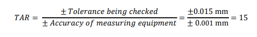
In this first example the TAR = 15 is acceptable as it is greater than the requirement of four. Based on this rule, the outside micrometer is an acceptable choice for the measuring equipment. For a second example, let us look at the calibration of this same outside micrometer. The calibration is done using Grade AS-1 gage blocks. In accordance to ASME B89.1.9-2002, the tolerance for Grade AS-1 gage blocks up to 25 mm is ± 0.30 µm. The TAR is calculated as:
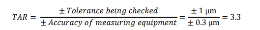
In this case, the TAR = 3.3 is not acceptable and different gage blocks should be considered. If Grade 0 gage blocks were used instead, with a tolerance of ± 0.14 µm up to 25 mm, the new TAR is calculated as:
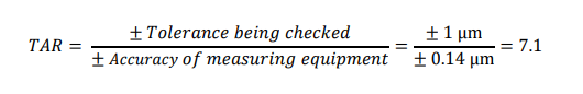
Following the TAR ≥ 4 rule, for this micrometer calibration, Grade 0 gage blocks are acceptable but not Grade AS-1.
The evaluation of measurement uncertainty stormed into commercial calibration practice in the late 1990s. As more and more calibration laboratories started calculating and documenting uncertainty, both in scopes of accreditation and in calibration certificates, the practice of using TAR calculations began to be replaced with the test uncertainty ratio, TUR. The use of simple acceptance and rejection decision rules with TUR requirements are now found in many national and international standards for the calibration of measuring equipment. For example, the American national standard for micrometers, ASME B89.1.13-2013, states that when assessing conformity with specification, a simple acceptance decision rule with a TUR ≥ 4 shall be used.
TUR is calculated in a similar manner as the TAR; however, an estimate for the measurement uncertainty is needed. Evaluation of measurement uncertainty is beyond the scope of this technical bulletin; however, we can take advantage of examples published in standards, for example the ASME B89.1.13 standard includes an example uncertainty evaluation for the same micrometer example discussed above – a 0-25 mm outside micrometer being calibrated with Grade 0 gage blocks. In that example, the estimate of the measurement uncertainty is ± 0.25 µm. The TUR is calculated as:
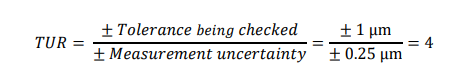
The TUR ≥ 4 requirement is therefore narrowly achieved, and a simple acceptance decision rule can be used. In this example, the TUR = 4 when the TAR = 7.1. The TAR is generally larger than the TUR as measurement uncertainty includes all sources of variation and not just the specified accuracy of the measuring equipment. Both TAR and TUR can be useful in measurement practice. The TUR is most useful in selecting calibration providers, as ISO/IEC 17025 accreditation forces all laboratories to evaluate and document uncertainty. The TAR is quite useful in selecting new measuring equipment.
Previously Featured on Mitutoyo's website.
Established in 1963, Mitutoyo offers a full product line of precision measuring tools including calipers, micrometers and indicators, as well as instruments and equipment. Mitutoyo is the leading metrology company in the world and is committed to developing breakthrough technologies for its comprehensive range of dimensional measuring tools, instruments and systems. Mitutoyo continues to develop the most advanced and sophisticated metrology equipment available.


To request a quote, please login to your existing account or register a new one. This helps us provide you with a personalized experience and keep track of your requests.