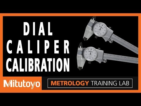
VIDEO: Metrology Training Lab–Dial Caliper Calibration
In this episode of the Metrology Training Lab, Mitutoyo revisits the calibration of calipers and looks at a specific issue with dial caliper calibration.
In this episode of the Metrology Training Lab, Mitutoyo revisits the calibration of calipers and looks at a specific issue with dial caliper calibration.

In this episode of the Metrology Training Lab, Mitutoyo revisits the calibration of calipers and looks at a specific issue with dial caliper calibration.
Dial calipers use little gears, and the gears can wear.
Errors are possible within a rotation of the dial that you won’t see if the calibration method results in the pointer always being at the 12:00 position.
The ASME B89.1.14 standard requires some test points that put the pointer in additional angular positions.
Previously Featured on Mitutoyo America Corporation's YouTube channel.
Hello, I'm Jim Salsbury with Mitutoyo America Corporation and welcome to the Metrology Training Lab. In this episode we’re going to revisit the calibration of calipers and look at a specific issue with dial calipers.
In a past episode, we thoroughly covered the calibration of calipers, following the guidelines from the American National Standard ASME B89.1.14. In that episode, we focused on the more popular digital caliper, and we missed discussing an issue that is important to consider for dial calipers.
So first, let’s do a very brief review and summary of the general calibration method for calipers. I’m going to first use a digital caliper, and I’m not going to try to be particularly precise in this example, so please forgive me for that.
For the outside jaws, we take a series of measurements over the measuring range, one inch, two inch, four inch, six inches and we also vary where we are across the jaws. Then we do an inside measurement, one inch like this then for the depth bar we do a measurement like that. This caliper has a step function so we do a measurement like that and then to make sure that we don't have any problems with small inside knife edges, you measure a two hundred thousandths ring gauge like that.
I'm going to now repeat some of those same measurements this time using a dialcaliper. I want you to look closely at the angular position of the pointer in the dial during these measurements. So I'm going to repeat the same outside measurements as I did with the digital caliper so at one inch and notice that the dial is at the 12 o'clock position. I go to the two inch, once again the 12 o'clock position. I go to four inches again, 12 o'clock position and go to six inches again 12 o'clock position. Inside measurements once again the same position. I could show you that for the depth and step and for the ring gauge all of those the pointer would be at the 12 o'clock position on the caliper.
Now dial calipers use little gears inside and the gears can wear. It's possible for there to be errors within a rotation of the dial that you won't see if the calibration method results and the pointer always being at the 12 o'clock position like you just saw. For this reason the ASME B89.1.14 standard requires some test points that put the pointer in additional angular positions so they're not always at 12 o'clock position.
So for an example I have two gauge blocks that are rung together here. So this is a .125 gauge block and this is a .150 gauge block. These are standard blocks from any set of gauge blocks so most people have these. For this style caliper, this in size caliper, with the .125 block if I was to measure that, I should be at the three o'clock position like you see here. If I measure the .150 block, I should be at the six o'clock position like you see here, and if I measure both blocks that are rung together should be at the nine o'clock position.
So these two gauge blocks rung together give me three additional easytest points. Not too difficult to test the accuracy of the caliper with the pointer in different angular positions. The ASME B89.1.14 standard does not prescribe specific test points so you have lots of flexibility, here but wewanted to show you at least one option one way that does the job and it's prettyeasy to implement. That's everything for this episode. Thank you, I'm Jim Salsbury and I'll see you next time from the Metrology Training Lab.
Established in 1963, Mitutoyo offers a full product line of precision measuring tools including calipers, micrometers and indicators, as well as instruments and equipment. Mitutoyo is the leading metrology company in the world and is committed to developing breakthrough technologies for its comprehensive range of dimensional measuring tools, instruments and systems. Mitutoyo continues to develop the most advanced and sophisticated metrology equipment available.


